Week 34
Monday
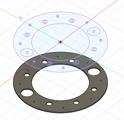
Lamination Station
As part of our new upgraded float, we will be making an upgraded Nut Plate. This will be heavily upgaded for strength, as the nut will be bolted on instead, due to an unfortunate failure at regionals the Epoxy joint will not cut it anymore. This means that the joint will be strengthened, and the weakest link would most likely be the bond between the tube and the Nut plate. This is why I am laminating 1/4" acrylic plates, to give us more surface area, and therefore a stronger bond overall. This is so that the nut is still the weakest link, which is fine as it is held in by bolts, which are easily replaceable.
Boring Math
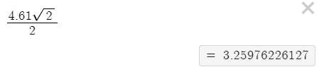
In addition to the upgraded Nut plate, we will be redoing our battery, as it also experienced unfortunate failures. This will come in the form of two PCB’s that will replace the resin printed end parts. This should allow us to have a better connection, that is more repairable, and also more reliable. For this, we now need to use KiCad as a CAD software, which is is not built for. This means that I have to do math to figure out where all of the peices should go. to do this, I had to figure out the X and Y offsets, in order to offset it from geometry in an imported DXF. The actual Math is Below.
Lathe Work
To complete the new float, we will also need a second piston. This means that I will be back on the Lathe. Today I only got to facing the end of the stock, and zeroing both axis. Tomorrow I should be able to get to turning the stock to diameter.
Tuesday
Battery Holder
Yesterday Scott and I were not able to figure all of the stuff out. Today, we ended up just making a new DXF, that actually lines up with the things. This simplifid the work that needed to be done in KiCad, which was nice as KiCad wasn’t designed for this type of work in mind. Fortunatly this new stratagy was WAY better, as it was essentally drag and drop onto the new DXF in KiCad. This new battery holder will be so much better as we won’t have soley soldered wires connecting everything. The traces and connectors will be much more reliable.
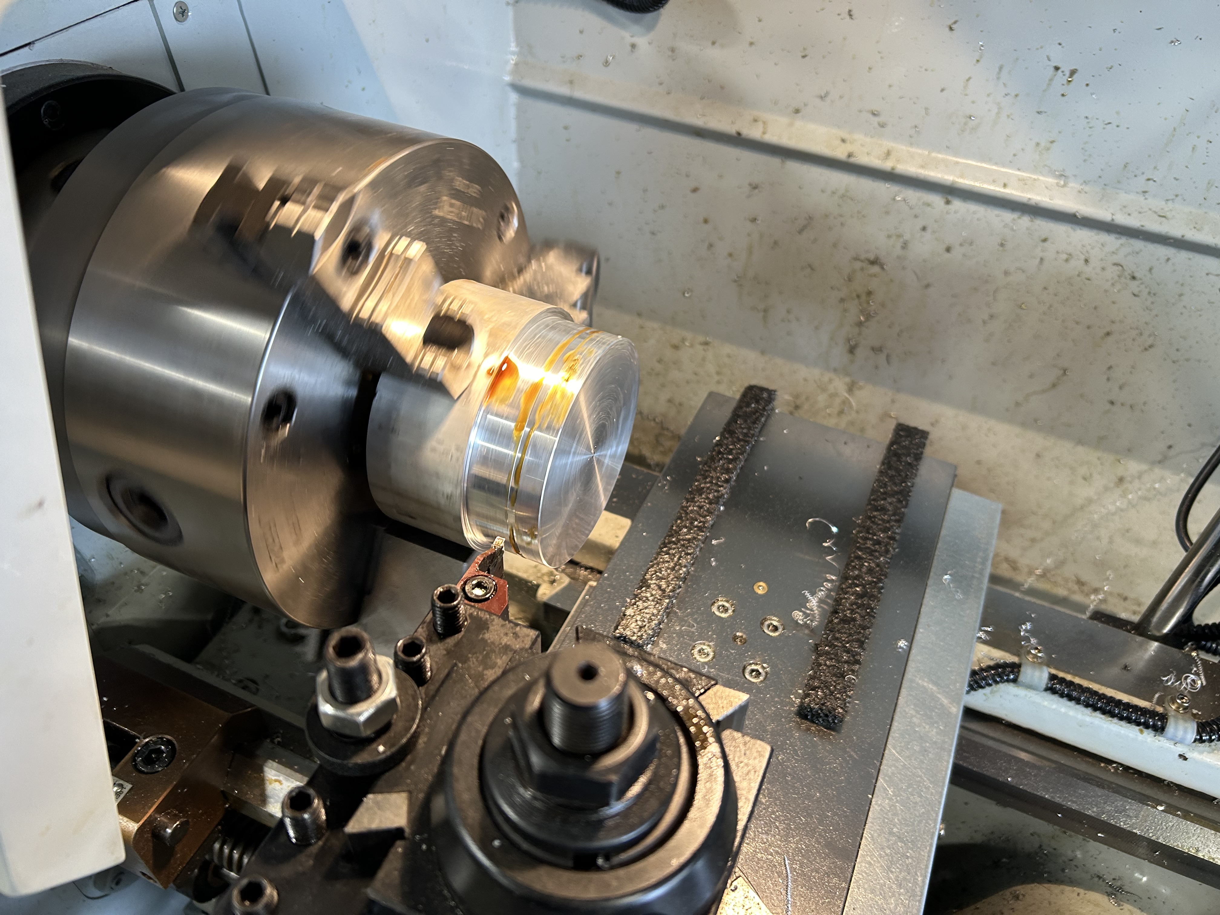
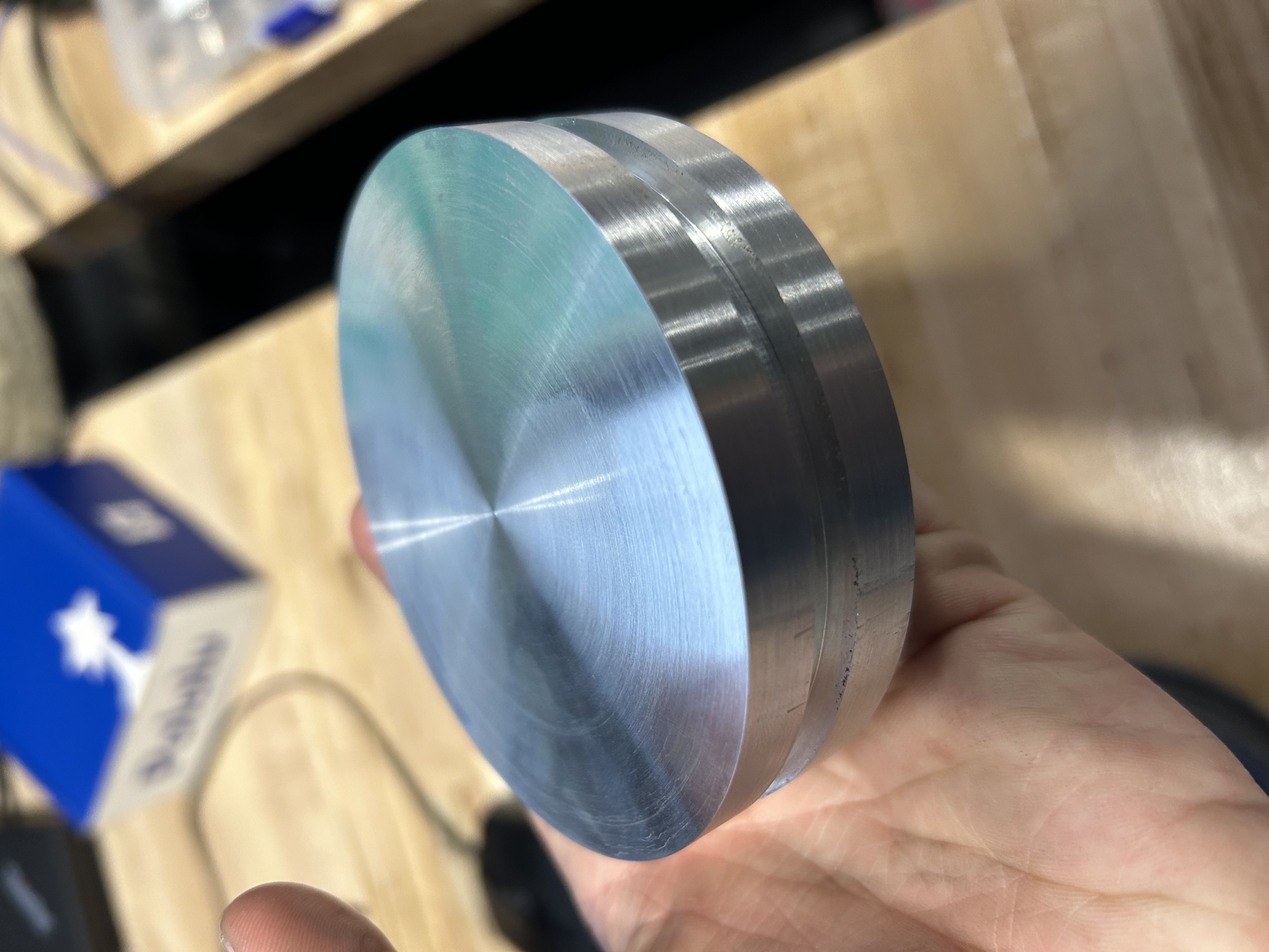
Piston
Today I started on the real turning of the piston. I turned the overall stock down to diameter, using a bunch of 20 thou passes with a carbide insert. Annoyingly Aluminum doesn’t chip right with these passes, and they make a bunch of springs, up to about 4 feet long which can get annoying at best, and terrifying at its worst. Tomorrow I will probably cut the grooves.
Wednesday
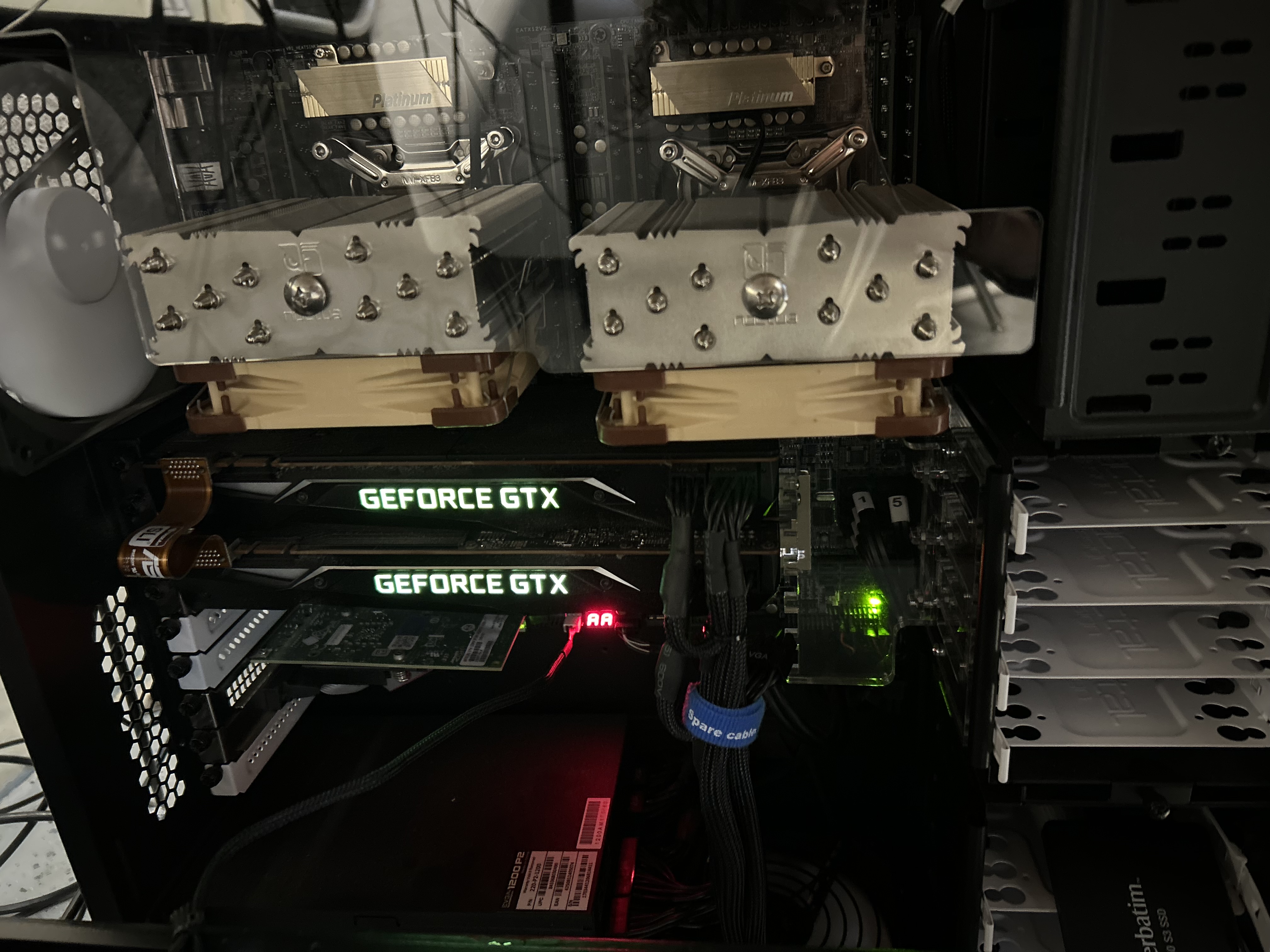
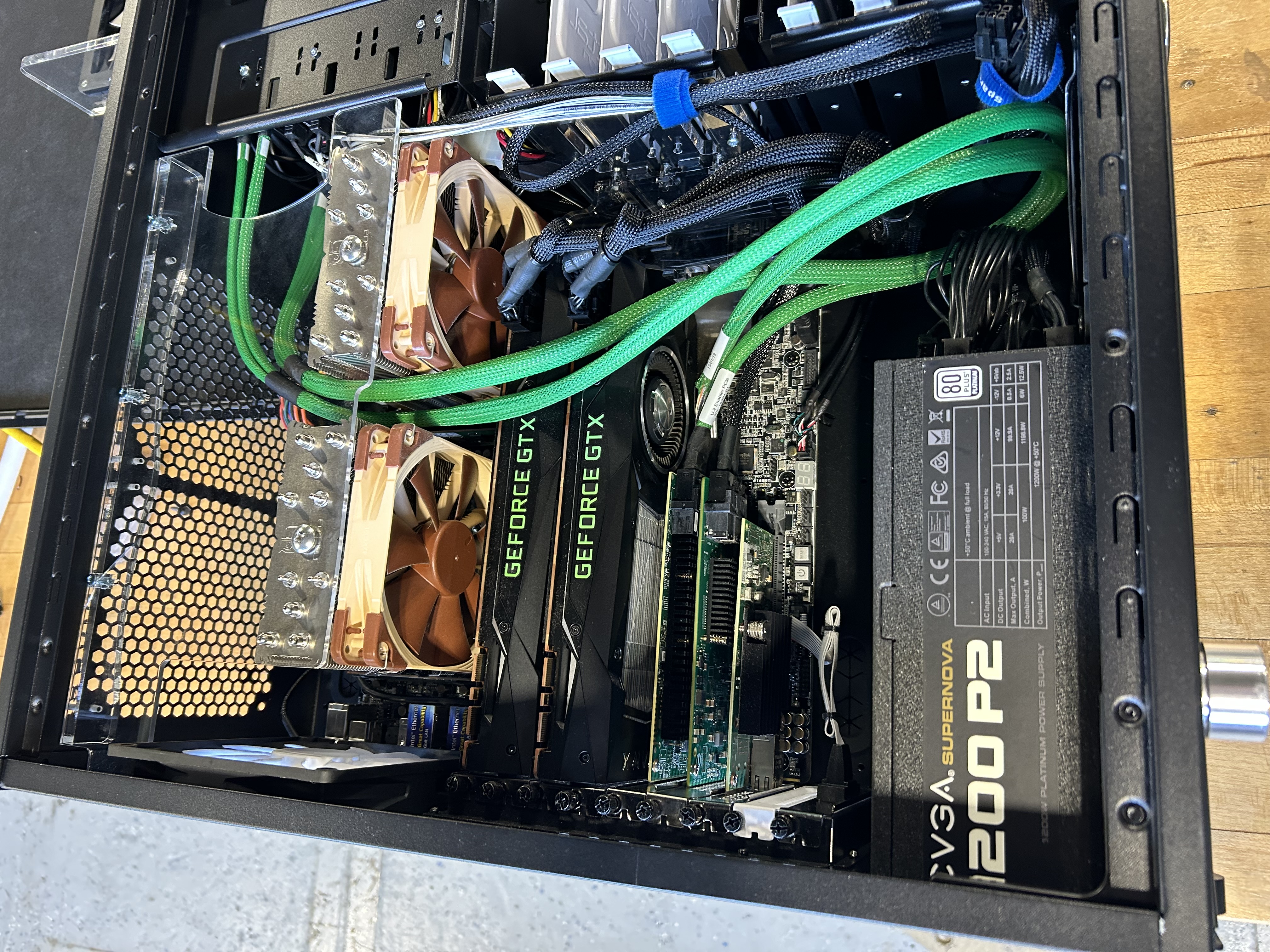
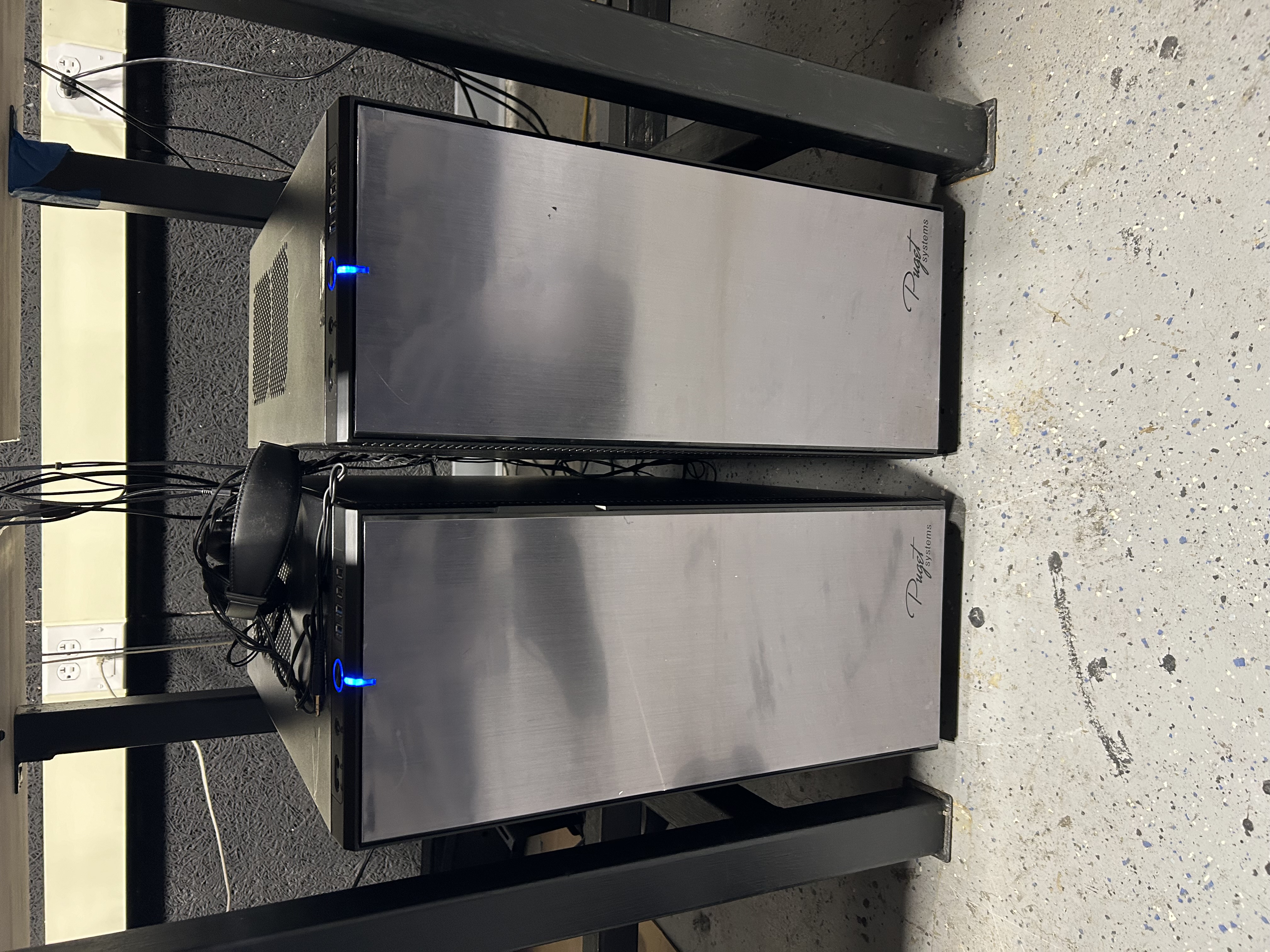
Computer
So my entire day got a little de railed, as the doations from the Toyota Research institute. For me the most exciting things are the two high end workstations that we got. In them are 2 Xeon ES-2690 CPU’s, 128 GB’s of DDR3 ram, and 2 NVIDIA Titan Xp GPU’s in SLI. One of the CPU’s msrp is about $2000, which is absolutely insane. These are definitly the nicest systems that I have seen in person. I don’t have much hope of maxing them out, but Scott and I might be taking on the golf cart next year, so AI training might happen. For me, I might be able to do some crazy CFD now, but i’m not very sure.
Thursday
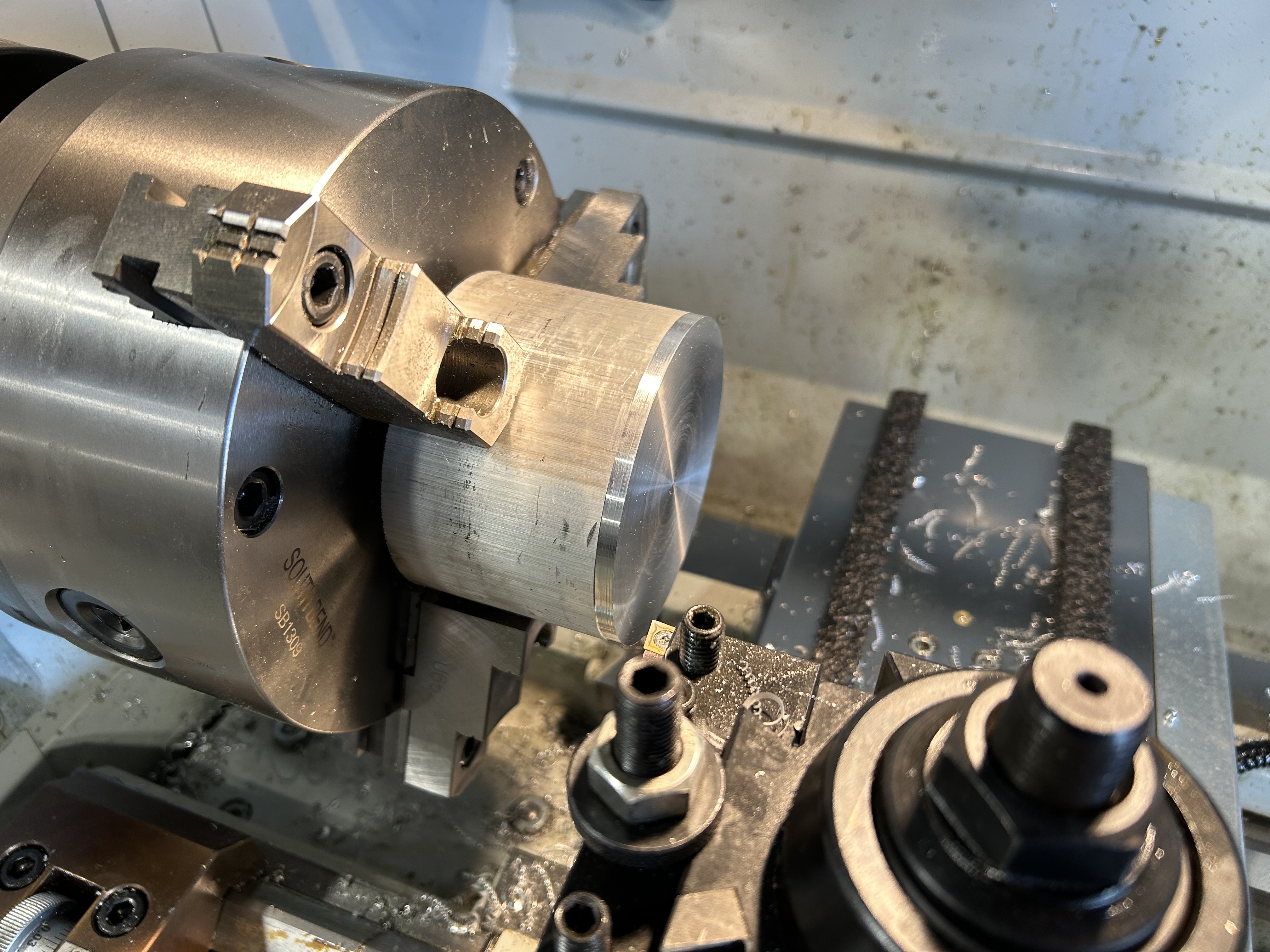
Piston Continued
Today I turned the groove for the O-ring. To do this I had to put the parting tool in its holder thingy, and then center it, using a cool scale trick. After this I was able to cut the groove. Out of the all of the tools on the lathe that I have used, parting tools scare me the most, as they are meant to essentially plunged into metal. Also they make scary noises when restarting sometimes. I got the grooves cut and all nice, so then I made a very NOT sketchy setup on the horizontal bandsaw to cut it off, because the parting blade isn’t long enough. I then threw it back in the lathe to clean the back side up from the cut. It is important to note that because I did this, It is not straight at all, for this reason the Origonal surface that I faced will be the top where all of the things will be mounted to. The next step will be to put this thing in the mill and then program all of the screw hole into it.