Week2
This was the first full week in school that we had, and we definitely felt it. The humidity has been down significantly the past couple of days which was quite nice. This week I was taken off of the fish feeder repairs to work on the Float with Scott Campell which I will probably be doing for the next school year, and the fish feeder was thus handed off to Sacha Silva.
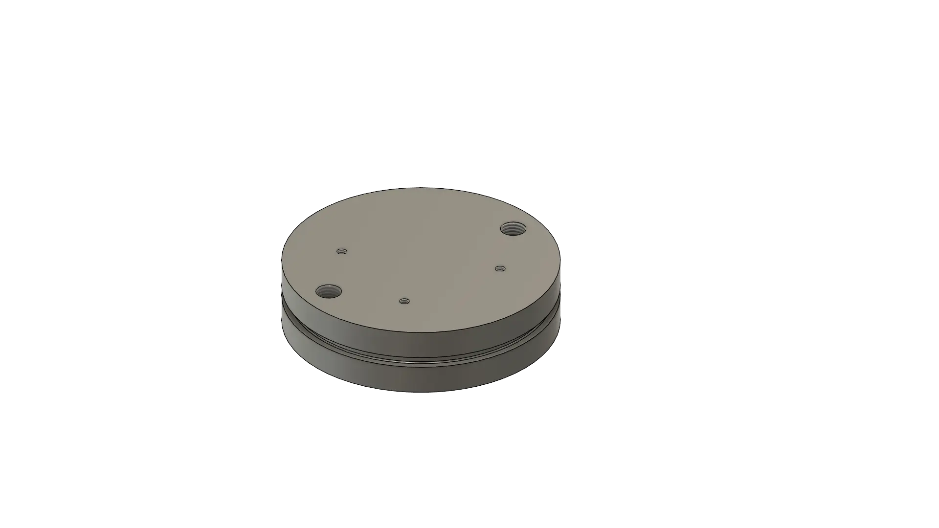
The Float is one of the coolest pieces of hardware I have designed and built. It changes its volume which therefore changes its density making the craft rise and sink in the water. Commercially this is done by pumping oil into different containers. one which has a fixed volume, and a rubber bladder that increases the volume of the craft, therefore density. We however chose to physically move the bottom of a cylinder up and down to create the volume difference. Last year this was done by using a resin printed piston with a dynamic o-ring seal, which was quite the pain to get working. However we now have it working properly and will most likely stick with this approach, with a slight modification. This year we will be turning a solid aluminum piston, so we can easily interchange motor holders, allowing for easy motor swaps. This is a large problem we ran into last year as we had to change motors quite often due to the motors not being quite powerful enough to overcome the 10 ft water column. We need to machine it out of metal, due to the fact that resin prints do not work very well with threaded inserts.
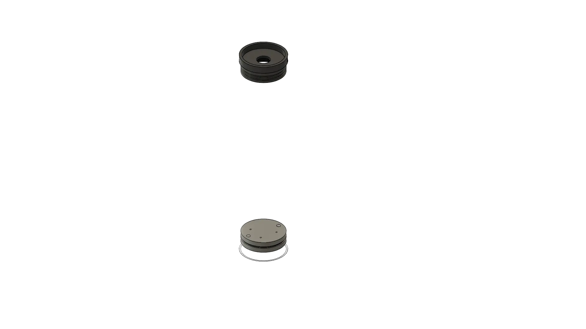
The fact that the piston is metal also allows us to create anti-rotation pins which allow us to do some fun cable management, but more importantly prohibit the rotation of the piston within the tube. These rods are much more complex than that however as one rod needs to be hollow, to allow for the afformentioned fancy cable management, and the other one needs to be more solid, to allow for mounting magnets on the other end to interface with the hall effect sensor we use for detecting where the piston is in its travel. This has made making decisions about what to get nearly impossible as I need to order 2 different parts. This is also made harder by the fact that the shop doesn’t own any NPT (National Pipe Thread) taps, making it so that I would need to buy an unthreaded pipe and turn it to diameter and thread it myself ( which is totally doable, just more work than using intgrated threads). Then however comes the difficult decision of choosing what to order on the solid pipe, as it would ideally be the same diameter, and material, however the float would probably have a siginficant list as the solid rod weighs significantly more. These conundrums have made it so that I have a new plan every five minutes, however better to figure it out now than on the fly in april! Ideally I buy stock that is roughly the right size and hollow, turn the outside to diameter, and cut threads for the piston. Then for the magnets I bore out the inside so the bottom one has a ledge to sit on, and then stick a spacer in there and put the top magnet on, then to make it fancy I tap the inner bore, and make a cap that screws on. I am still hoping that this will be possible but you never know!
Of course after writing this entire blog post I had an idea that I kind of like. I could possibly take some thick walled stainless pipe, and chop off the threads (Because why would you sell 1/8th inch unthreaded schedule 80 pipe) and use that as my stock. Its a bit pricier but it makes much more sense, is a lot simpler, and also preserves the balance of the float much more.
Overall this week has been pretty productive, and I am very excited to start working on the new float. If you enjoy more of the electrical aspect of these sorts of projects you can check out the work that my partner Scott Campell is doing on his side of the Float. Next week we are probably looking at starting to come up with ideas about the electrical housing, and most likely waiting for my order of metals to arrive. While that is happening I can get a decent enough familiarity with the lathe, as that will be about 95% of the machining on this project, which I am looking foreward to quite a bit.