Week 18
One thing that I have learned with doing the hardware for these projects, is that everything feels like its crawling, until one week all of the hardware is pretty much done. This was one of those weeks. On the float there were two main design challenges that were properly hard. The first was the Piston assembly. This was mainly hard because of the dynamic o-ring seal, which was time consuming, and because of the anti-rotation rods, which came out very nicely. The second was the battery holder. This was hard because of the integration of the battery clips, which required very accurate 3d printing, and the abstractness of the whole thing was also very challenging. This week these two things came to fruition in the fullest form. This marks the beginning to the end of the work on the hardware of the float, but no where near the end of the work on the float.
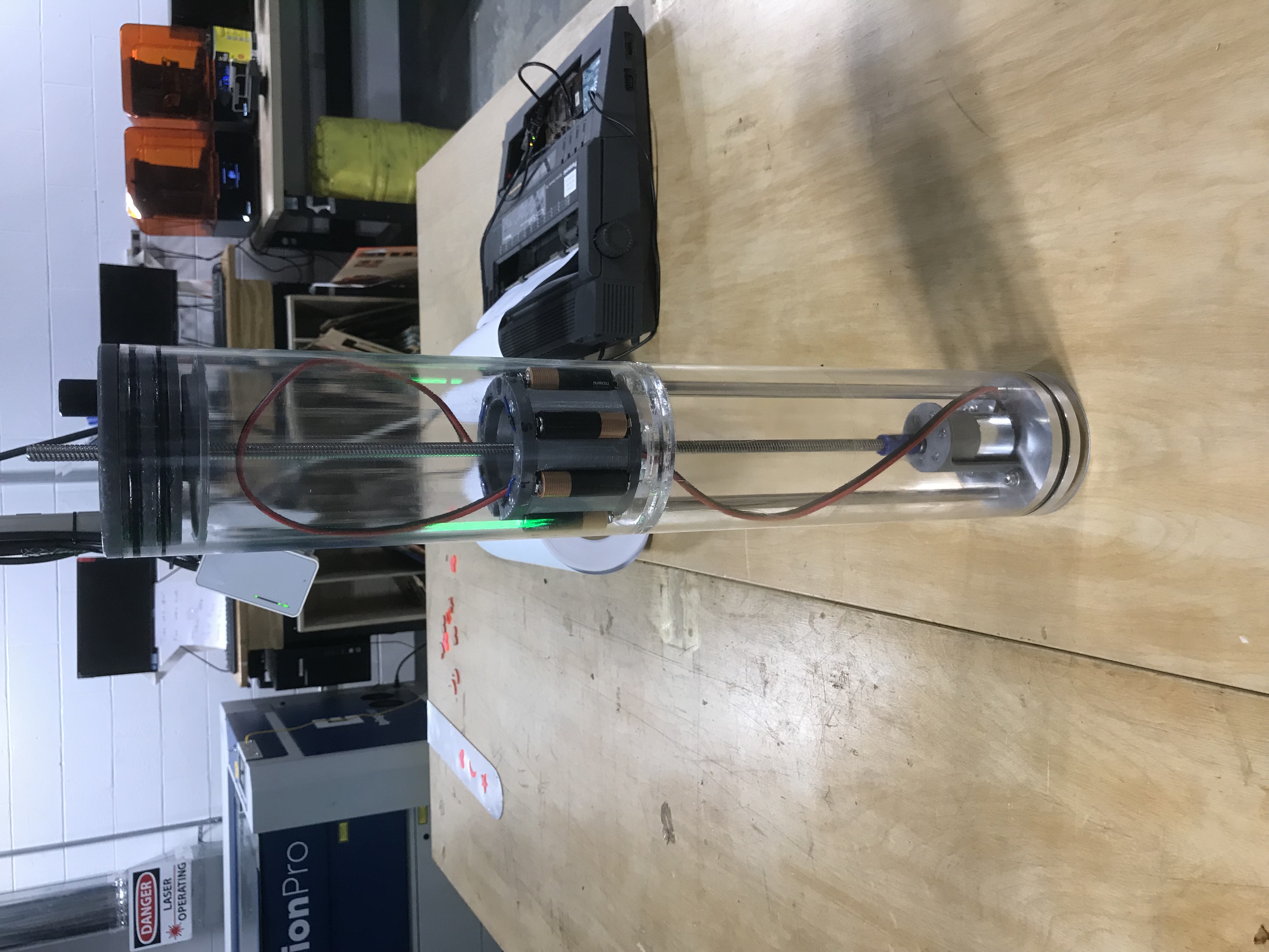
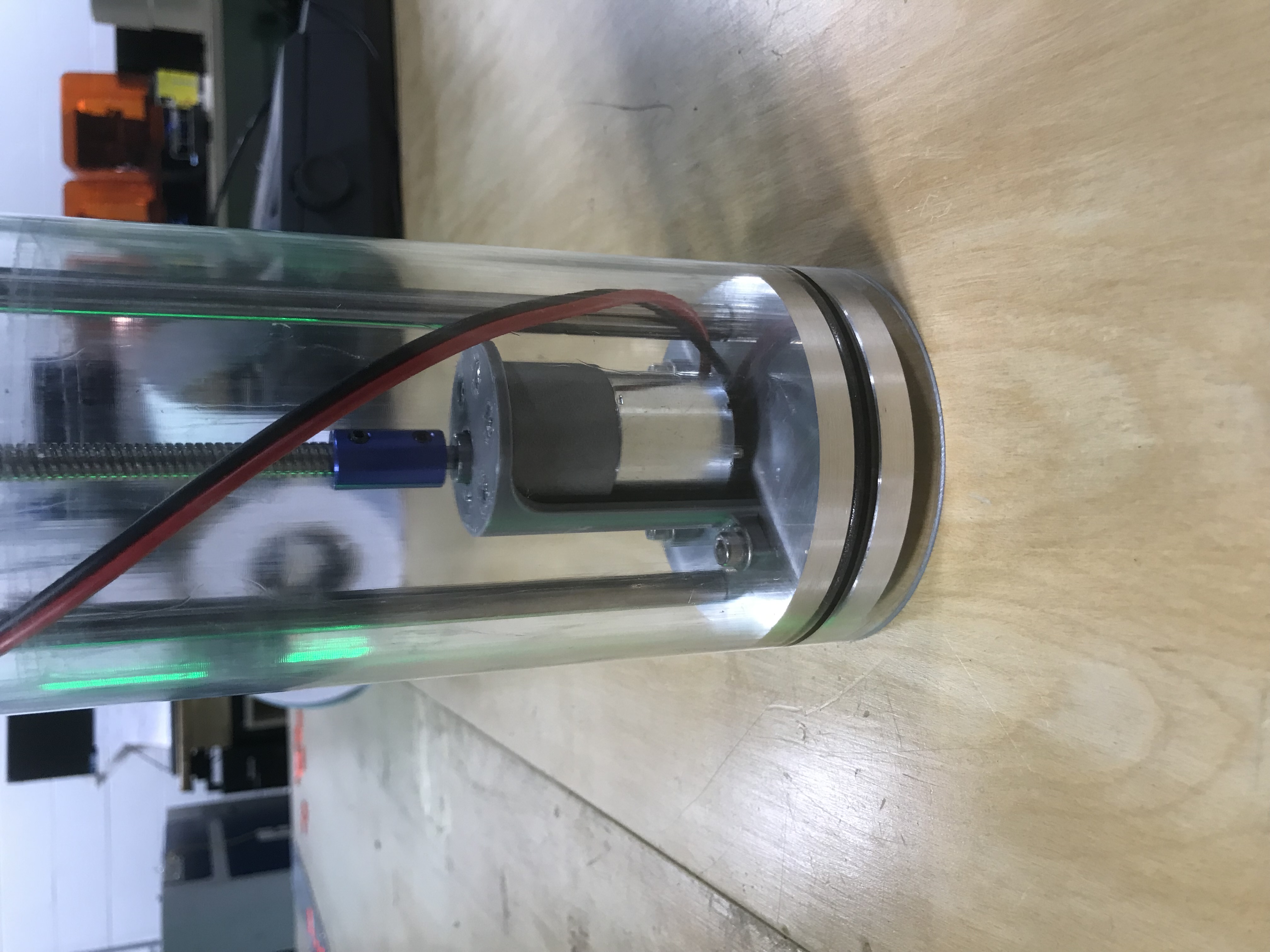
Piston
This week I was able to acrylic weld in the doubler plate that allows me to inset the brass bushings for the anti-rotation rods. I didn’t do the best of jobs but it does definitly work.
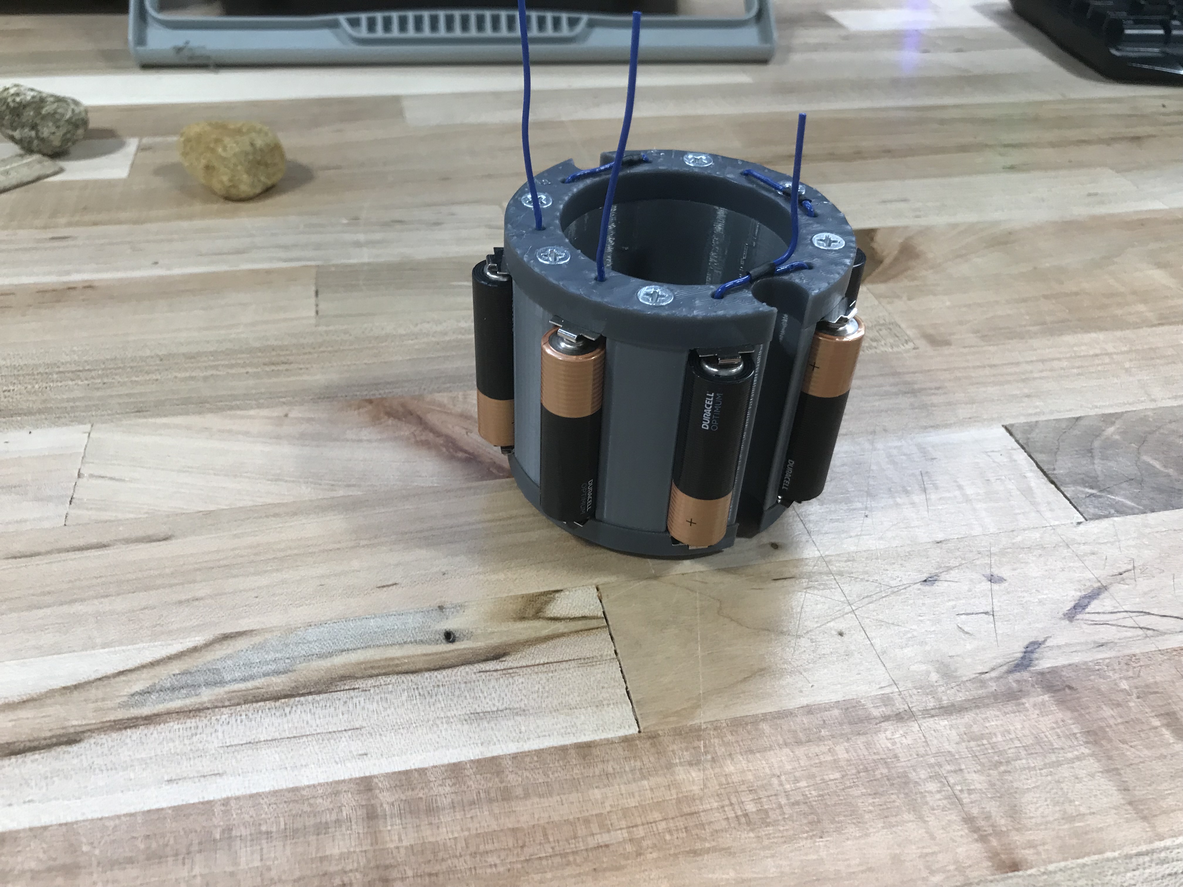
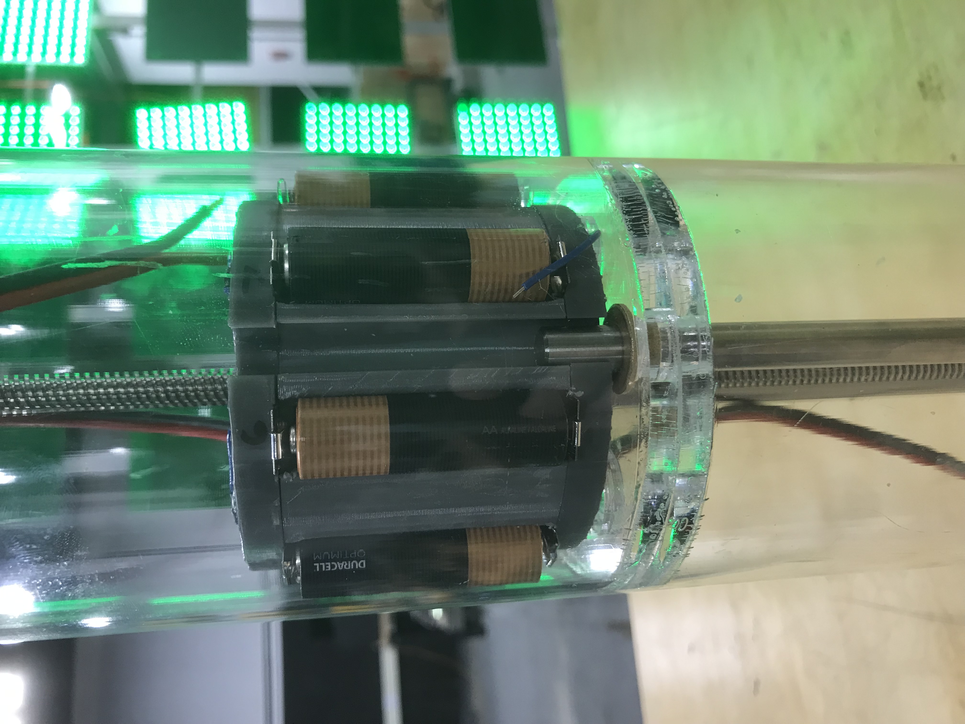
Battery Holder
I have no idea why I put off soldering the wires for it so long, as it was fairly easy, with the only difficult spot being the 3v tap for logic. Unfortunatly the labeling is bacwards to the tap, but that isn’t a huge problem, as long as we relabel it. We also tested if the amount of current that the battery can supply would be enough, especially when the motor is pushing against about 60-70 pounds of force. Thankfully it works, but the battery will definitely need to be replaced fairly frequently.
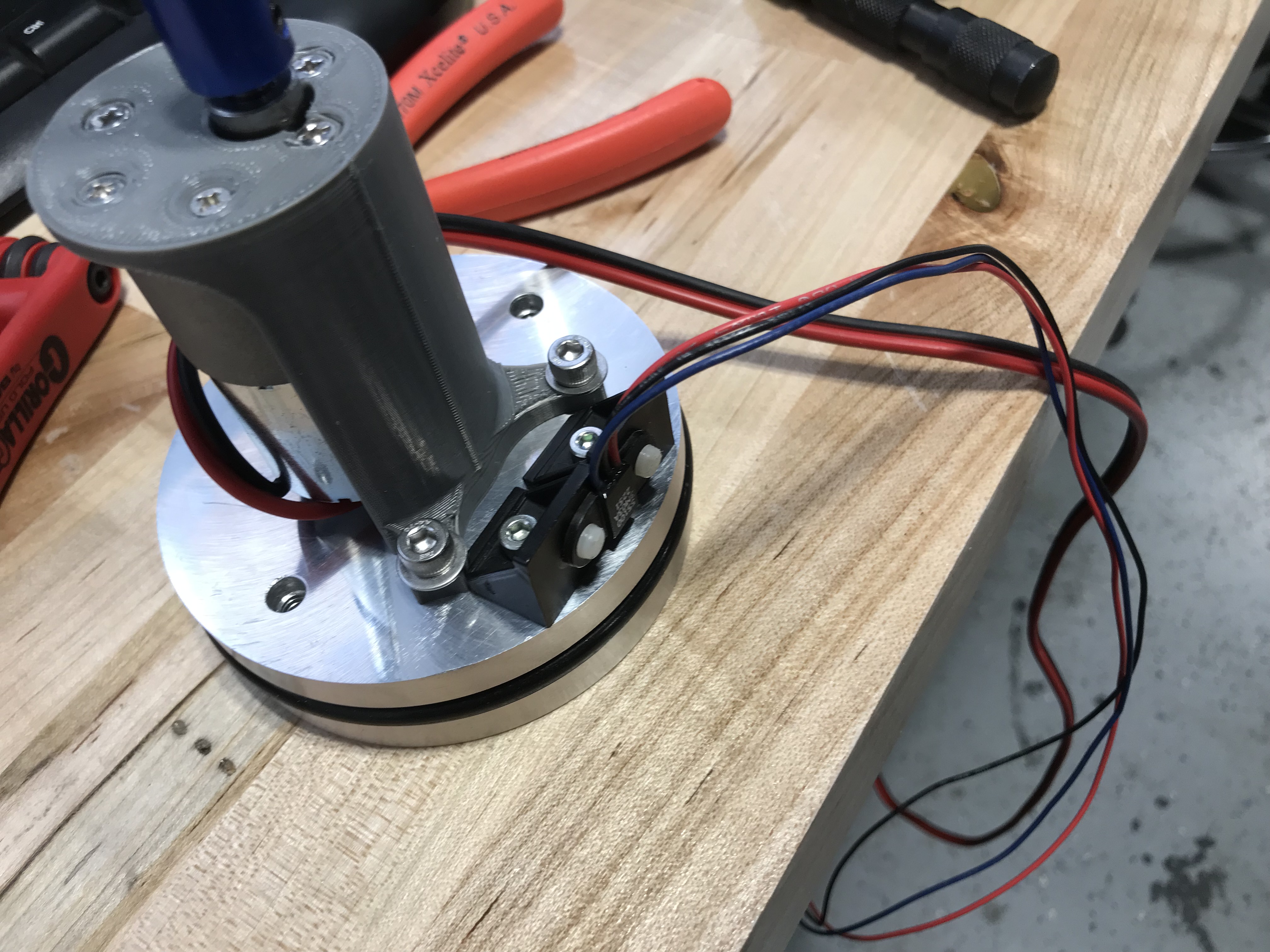
Hall Effect Sensors
Now with all of that stuff done, we started to think about how we were going to mount the hall effect sensors we use to sense the position of the piston. We debated a few ways, but we decided to go with the tried and true way of mounting the magnets on the outside, and the hall effect sensor on the inside. The magnets are held in a 3d printed part that is adjustable. Idealy everything is on the inside, but there was no real practical way to do this.