Week 13
This was a very exciting week as I finally got the floats piston seal working. This is very monumental for the float, as it means that we can start to assemble it, and also proves that it is possible for us to do it with the tubes that we have. The next order of buisness is to machine the piston out of aluminum. For the rest of the week I worked on the PCB mounting solution.
The first thing that I was thinking of was to laser cut a peice of acrylic that has stilts also cut out of acrilyic that holds the PCB horizontally in place. This seemed good at first as it was a very simple 3d solution, but as I would find out, was not.
The first idea had a few issues with it. Firstly, it was ugly, and secondly it didn’t keep the PCB with the top cap making it slightly dangerous to open the tube, as there is a delactate UFL connector on the microcontroller (These connectors are quite bad and are rated for about 30 unpluging cycles). To overcome this I would 3d print the peice that holds it in place, as I was going to put magnets in it, and the top cap. This would attach it to the top cap and prevent the delacate UFL connector from being violently riped out.
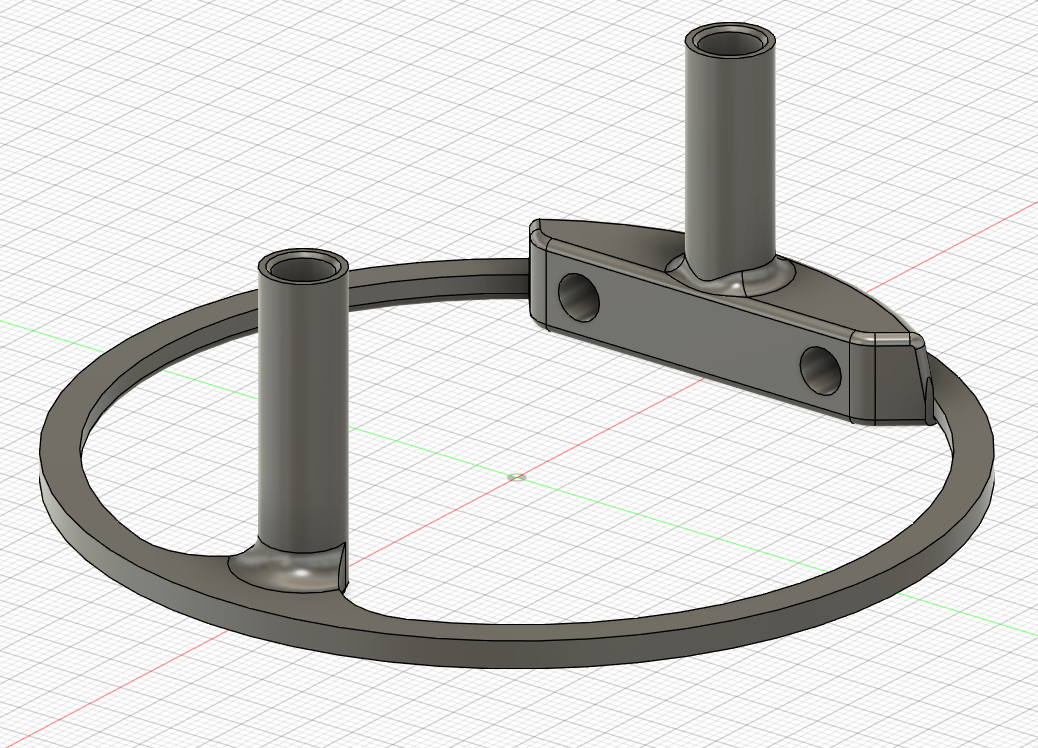
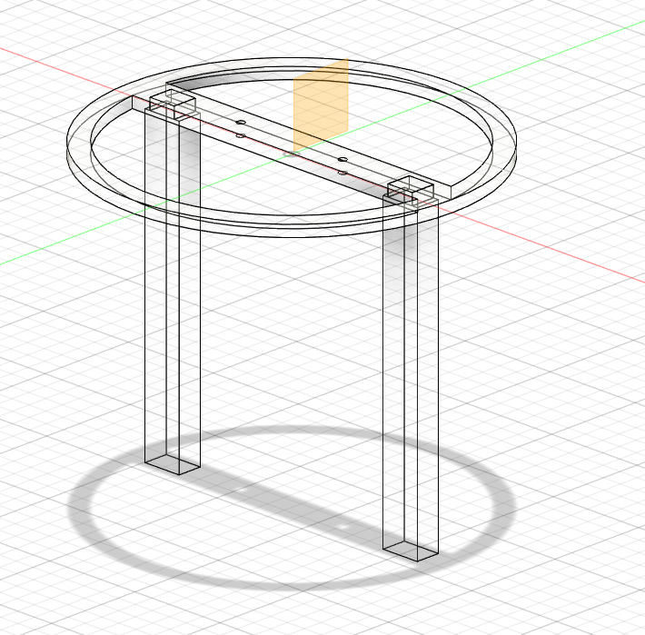
I then realized that there was one glaring issue. The fact that the board was horizontal, meant that it would get in the way of the lead screw. This fine as we have more than enough travel, but for optimal performance and capabity, I opted to hang the board vertically instead, as it wouldn’t put the electronics in harms way.